


General information
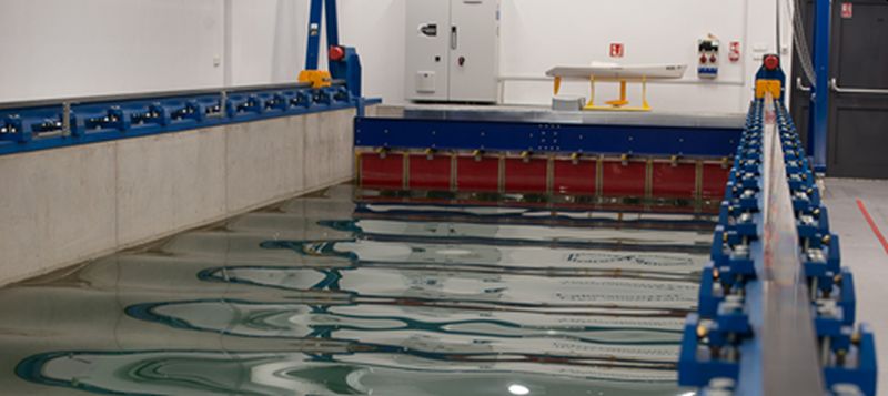
Hydromechanics Laboratory
Head of the laboratory
Mirosław Grygorowicz, M.Sc. Eng.
phone: +48 58 347 13 68
e-mail: snop@pg.edu.pl


|
Dimensions of the towing tank |
parameters |
|
length of the trough of the pool |
40 [m] |
|
inside width trough of the pool |
4 [m] |
|
Total depth of the pool |
3,75 [m] |
|
Depth from the free surface of the water |
3 [m] |
|
Length of the docking part |
5,5 [m] |
|
distance between runways |
4,27 [m] |
|
the length of the measurement area |
Resulting |
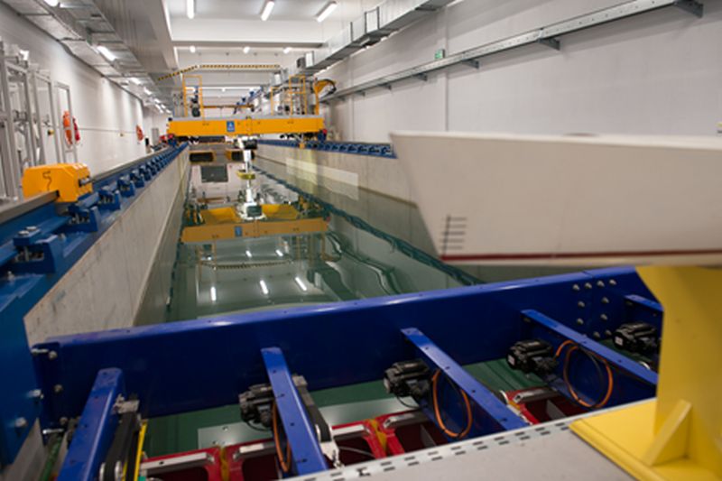
Towing tank – instrumentation
1. Towing platform with the tracks
a. Application of the model towing platform
The main task of towing platform on the towing tank is to carry out standardized tests of models such as:
- resistance,
- static in still water,
- static on the wave,
- dynamic in the still water,
- dynamic on the wave,
- propellers - measuring torque and stress.
b. Technical characteristics of the towing platform
|
|
Parameters |
|
The mass of the platform when ready for testing |
~3 [t] |
|
Speed range the platform |
0÷2,5 [m/s] |
|
Continuous adjustment of the speed of the platform |
0,1÷2,5 [m/s] |
|
crawling of the platform |
10 [cm/s] |
|
Permissible fluctuation of the set speed of the platform |
± 3,2 [mm/s] |
|
Max. acceleration of the platform |
±1 [m/s2] |
|
The installed power of the drive |
|
|
constant |
17,84 kW |
|
instantaneous |
26,76 kW |
|
Braking systems of the platform |
|
|
drive system |
- 1 m/s2 |
|
electrohydraulic brakes in emergency mode |
- 2 m/s2 |
|
Breaks on the rails |
approx. – 3 m/s2 |
|
fixed end stops on the ends of runways |
approx. -5 m/s2 |
- Control of propulsion is provided by a Variable Frequency Drive System of AC servo motors with a desktop PC or a portable cassette.
- Acceleration (delay) of the platform is controlled by the control system of the drive.
- The platform is powered by a guide cable.
- Running gear are the 4 systems consisting of an engine, motor reducer and driving wheel.
c. The supporting structure of the platform
- Towing Platform was made as a platform construction (welded-bolted) with closed aluminium profiles.
- The construction of of the platform has a rectangular shape. It is divided into two (2) segments resting on four (4) running wheels.
- Inside the platform, on the so-called measurement space there are guide rails, on which measuring and supporting devices will be installed. On both sides of the measurement space the supporting structure of the platform was covered with a removable floor.
- On the construction of the platform some universal holders for mounting of the measuring equipment are provided.


2. Plate wave generator
Plate, 8-segment regular and irregular wave generator (with given spectrum of waves) with a maximum height of 0.25 m was designed and made by Edinburgh Design;
Starting and implementing of the wave is done remotely from a computer using Njord software;
Enables generating of the following types of waves:
- Regular waves;
- Irregular waves – pre-defined spectrum or given by the user (build-in standard spectra: Pierson Moskowitz, ITTC, JONSWAP and Gaussian);
- Short and long breaking waves;
- Focused (concentrated) waves for simulating of the extreme phenomena;
- Complex waves from combined states of the sea;
- Imported from the file with time dependency eg. from the measuring buoy
- Waves generated under the angle;
- Waves fully defined by the user.
3. Set for measuring and recording of the waves
The set for measuring and recording of the waves consists of three basic elements
- wave probe;
- signal matching device;
- A wireless modem;
Measuring range: wave height: 250mm;
Registration of the regular and irregular wave profiles;
Possibility of installation on the crown of the pool or at the towing platform;
Type of the probe: resistive
4. Ternary balance (f-my CTO)
The X axis of the dynamometer is directed so that runs along the measurement tank, whereas the y-axis is directed crosswise. Maximum measured values of the Fx i Fy forces yield ±200N.
The rotation of the model along the Z axis (YAW) is generating the torque Mz , whose maximum value can yield ±40 Nm.
Block of the linear bearings mounted on a rotary head of the steering system allows smooth movement of the linear guide along Z axis. At the end of the linear guide is movable support, which is fixed to the model. With the aid of the steering system the model can be rotated with respect to the Z axis and set at an angle with respect the X axis with an accuracy of 1 degree.
The displacement of the upper plate of the balance with respect to the fixed bottom one (to the cart frame) is transmitted by a vertical guide It has a range of movement ± 150mm, and its swinging support is attached to the tested model. The vertical movement of the guide enables the trimming of the model during tests and in the cases when the waves are also used.


5. Dynamometer for the measurements of the resistance
a. Measurement ranges :
Range I resistance force 0-100N
Range II resistance force 0-200N
Range III resistance force 0-500N
Vertical range of the motion (Z) ±300mm
Horizontal range of the motion (X) ±150mm
Maximum exploitation overload 150% Fnom
Maximum static side force 100% Fnom

b. Application of the dynamometer
The dynamometer is designed to conduct research of resistance of the model on still water and on the regular and irregular wave in the model tank. The construction of the dynamometer enables its mounting on the thawing platform of the model tank as well as connecting to investigated model through a strain gauge. Dynamometer provides freedom of movement and can measure the resistance of a hydrodynamic model in still water and on the waves. In addition, it is possible to measure the immersion of the model.
c. The construction and operation of the dynamometer
The dynamometer is capable of measuring hydrodynamic resistance through removable strain gauge force transducer of various measurement ranges. This allows for the selection of the transmitter with the optimal range of the expected value of strength. Other elements of the dynamometer allow for such a connection of the towing platform with a model to maximally decrease its impact on the test object and at the same time ensure a smooth measurement in the axis of tow.
The basic parameters of the dynamometer are:
- mounting system of the dynamometer to the towing platform ,
- body with a sliding element that allows free movement of the object in the vertical axis,
- The dynamometer attached to the support of the test sample providing free oscillations of the test sample, and little flexibility in the horizontal axis transverse to the direction of tow,
- damping system along the measuring axis to provide mitigation of momentary overloads during acceleration and deceleration of the towing platform and during the tests on the wave,
- a strain gauge transducer,
- wire displacement transducer to measure the immersion.
Due to the fact that the dynamometer ensures a relatively large freedom of movement of the sample, it is required to use additional devices to keep it in the towing axis while having minimal impact on the measured quantity. In the most common cases, it is performed using two guides, the bow and stern ones, that align the test sample along the direction of the tow.
6. Dynamometer for testing of models of propellers
Measurement ranges :
- Torque on the measurement shaft: ±5Nm
- Thrust: ±200N
- Revolutions on the measurement shaft ±2000obr/min
- Max. Immersion of the axis the measurement shaft 300mm
(that corresponds to the ITTC requirements for the model of the diameter of 200mm)

7. Balancing machine - a device for the measurement and calculation of the center of gravity and moment of inertia
Technical data:
- maximum width of the balanced models Bmax = 0,5 m
- maximum length of the balanced models Lmax = 3 m
- The nominal weight of the balanced models Δnom = 200 kg
- maximum weight of the balanced models Δmax = 300 kg

8. Systems for data acquisition
Modern systems including:
- Cassette core (PMX-high-HBM and DNA-PPC8-1G f-my United Electronic Industries), which allows, together with the applied modules, for recording analogue voltage signals, the differential ones to handle the strain gauge, universal counters, serial ports, etc. Data Transfer is via a wired or wireless Ethernet.
- Specialized software for creating measurement applications (Catman f-my HBM and DasyLab f-my MeasX)
9. The system is based on high-speed cameras to determine the position of the 6D object
Qualisys motion capture system consists of digital capture devices (cameras) and a user-friendly, windows-based software (QTM). The reflective markers which reflect infrared light emitted from a camera mounted on the model. The 2-D position of each marker is determined with high precision by the signal processing algorithm inside the camera. Through the combination of 2-D data from several cameras, software QTM (QTM) calculates the position of the 3-D markers. It is also possible to obtain a 6-DOF data in real time for the analysis of roll-pitch-yaw ship model.
Depending on the configuration of the model in the pool, it is sufficient to mount only 2 to 4 cameras. The cameras can be placed on a towing cart, which enables aligning of the model and the markers.
Parameters:
- High sampling frequency – do 10000 Hz;
- Large area of the measurement;
- Handling of both passive and active markers;
- Integrated functions of recording and analysis;
- Simultaneous tracing of a few models;
- Analog output 6DOF;
- Wireless tracing of the models that does not interfere their motion;
- Module system that enables future expansion;
- Mobility by using of laptops;
- Real-time 6DOF data through Ethernet TCP/IP;
- Possibility to modify the camera.
10. One-spindle, 5-axis CNC milling machine
The milling machine (f-my Fanum) will be used to fabricate models of investigated objects. The main parameters of this device are:
- The number of interpolated axes 5;
- Step of the X axis – transverse mm 1900;
- Step of the Y axis – longitudinal mm 4000;
- Step of the Z axis – vertical mm 700;
- Rotation range around vertical axis–C axis +/- 360°;
- Rotation range around horizontal axis–Aaxis +/-115°;
- Maximum speed of the motion along the X and Y axes m/min 60;
- Maximum speed of the motion along the Z axis m/min 40;
- Maximum speed of the motion along the A and C axes rev./min. 50;
- Storage strip mounted at end edge of the table, with 8 slots for tools;
- PC with the screen for communication between the operator and the machine;
- A work piece measuring probe;
- Probe for measuring of the tool length and its diameter;
- CAM software to generate the trace for the tool in 5 axes;
- Complete installation for dust extraction (dust collector filter, pipes, shaped fittings, mounted)
Together with the milling machine the CAD – SolidWorks and CAM – SolidCAM software are available.
